1. Understand the Requirements of Your CP System
Before selecting the cable, it’s important to understand the specifics of your CP system:
- Structure Size and Dimensions: Larger structures may require cables that can handle higher currents.
- Soil Resistivity and Terrain: Soil characteristics can influence the type of cable needed. Low resistivity soils (<5000 ohm-centimeters) often require specific types of cables.
- Corrosion History: Understanding past corrosion issues can help in choosing a more suitable cable.
2. Types of Cathodic Protection Cables
The most common types of cables used in CP systems include:
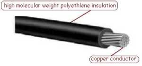
● High Molecular Weight Polyethylene (HMWPE) Cable: Known for its excellent resistance to abrasion, crushing, chemicals, oils, sunlight, and moisture. It is suitable for direct burial and submerged applications

High Molecular Weight Polyethylene (HMWPE) Cable
- Kynar/HMWPE Cable: Combines the toughness of Kynar (PVDF) with the durability of HMWPE, making it ideal for harsh environments

● Halar/HMWPE Cable: Offers enhanced resistance to chemicals and is often used in extremely corrosive environments

Cable Specifications
When selecting a cable, consider the following specifications:
- Size and Stranding: The American Wire Gauge (AWG) size and stranding determine the cable’s current-carrying capacity.
- Insulation Thickness: Typically measured in mils, thicker insulation provides better protection but can increase the cable diameter.
- Jacket Material: The material used for the cable jacket affects its resistance to environmental factors. Common materials include HMWPE, Kynar, and Halar
4. Application and Environment
Match the cable to its intended environment:
- Buried Structures: For pipelines and storage tanks buried in soil, cables with high resistance to moisture and chemicals are essential.
- Submerged Structures: For applications involving water, such as marine structures or water tanks, ensure the cable can withstand prolonged exposure to moisture and possibly saltwater
5. Standards and Compliance
Ensure that the selected cable complies with relevant standards and regulations:
- ASTM Specifications: Cables should meet specifications such as ASTM B-8 for stranded copper conductors.
- NEC Compliance: Check for compliance with the National Electrical Code (NEC) for safety and performance.
6. Manufacturer Support and Customization
Some manufacturers offer customization options, such as special insulation colors and specific jacket materials tailored to your needs. Additionally, reliable technical support and field services can be invaluable in ensuring proper installation and maintenance. For further details and product options,contact Blaqskye international.
Typical Cable Sizes and Specifications in Cathodic Protection (CP) Systems
In cathodic protection systems, different points of connection require cables with varying specifications based on their function, environmental conditions, and the amount of current they need to carry. Below is an overview of typical cable sizes and specifications used at various points in a CP system:
1. Between Anodes and Junction Box
Cables connecting anodes to a junction box typically need to be robust and resistant to the harsh environments they operate in, such as soil or water.
● Typical Size: 8 AWG to 4 AWG
● Insulation: High Molecular Weight Polyethylene (HMWPE) is commonly used due to its resistance to abrasion, moisture, and chemicals.
● Specifications: Stranded copper conductors, often with a single layer of insulation. For example, an 8 AWG cable with 110 mils of HMWPE insulation.
2. From Junction Box to Transformer Rectifier (TR)
Cables between the junction box and the transformer rectifier need to handle higher currents and are usually run through protected environments.
● Typical Size: 6 AWG to 1/0 AWG
● Insulation: HMWPE or Cross-linked Polyethylene (XLPE) for enhanced thermal and mechanical protection.
● Specifications: Stranded copper conductors, double-insulated cables may be used for additional protection. A typical specification might be a 4 AWG cable with 110 mils of HMWPE insulation
3. From Transformer Rectifier (TR) to Structure
The cables connecting the transformer rectifier to the protected structure are critical as they carry the CP current directly to the structure.
● Typical Size: 2 AWG to 4/0 AWG
● Insulation: HMWPE or Kynar/HMWPE combinations for environments with higher chemical exposure.
● Specifications: Stranded copper conductors with a robust primary insulation layer and possibly a secondary jacket for added durability. For instance, a 2/0 AWG cable with 125 mils of HMWPE insulation..
4. Between Test Post and Structure
Cables used between test posts and the structure are generally smaller since they are primarily for monitoring purposes rather than carrying high currents.
- Typical Size: 14 AWG to 10 AWG
- Insulation: HMWPE or Polyvinyl Chloride (PVC) for general environmental resistance.
- Specifications: Stranded copper conductors, typically with a single layer of insulation. A common example is a 12 AWG cable with 100 mils of HMWPE insulation.

Key Considerations
- Current Carrying Capacity: The cable size must be sufficient to carry the expected current without excessive heating.
- Environmental Resistance: The insulation material should provide resistance to moisture, chemicals, UV radiation, and physical damage.
- Voltage Rating: Cables should have an appropriate voltage rating for the CP system, commonly 600V for most applications
